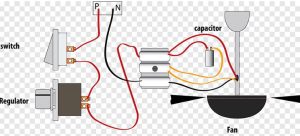
Ceiling fan wiring diagram with capacitor
Wiring a ceiling fan with a capacitor involves creating a circuit that allows for the fan’s motor to operate at different speeds. Capacitors in ceiling fan wiring are used to control the fan’s speed by storing and releasing electrical energy. Here’s a detailed explanation of a typical ceiling fan wiring diagram with a capacitor.
What are the components of a ceiling fan electrical system?
- Ceiling Fan Motor:
- The heart of the ceiling fan, responsible for driving the blades and creating air circulation.
- Capacitor:
- A device that stores and releases electrical energy, influencing the fan motor’s speed.
- Switches:
- There are typically two switches: one for controlling the fan’s speed and another for turning the fan on or off.
Wiring Diagram:
Ceiling Fan Wiring Diagram with Capacitor
- Wire Colors:
- Black or Red: Live or Hot wire.
- White: Neutral wire.
- Green or Bare Copper: Ground wire.
- Connections:
- Ceiling Fan Motor:
- Connect the live wire (black or red) from the power source to the live wire of the fan motor.
- Connect the neutral wire (white) from the power source to the neutral wire of the fan motor.
- Connect the ground wire (green or bare copper) from the power source to the ground wire of the fan motor.
- Capacitor:
- Capacitors often have three terminals labeled as L (Line), F (Fan), and C (Common).
- Connect the live wire (black or red) to the L terminal of the capacitor.
- Connect the live wire (black or red) from the fan motor to the F terminal of the capacitor.
- Connect the common (C) terminal of the capacitor to the neutral wire (white) from the power source and the neutral wire from the fan motor.
- Switches:
- The speed control switch is usually a rotary switch with multiple positions (Low, Medium, High). Connect it to the corresponding terminals on the capacitor (L, F).
- The on/off switch is wired in series with the power source and the fan motor to control the overall operation.
- Ceiling Fan Motor:
Operation:
- When the fan is turned on, the capacitor releases stored energy, influencing the motor’s speed based on the position of the speed control switch.
- The on/off switch controls the overall operation of the fan.
Note:
- Always turn off the power at the circuit breaker before attempting any wiring work.
- Follow the manufacturer’s instructions and guidelines for your specific ceiling fan model.